|
|
Glen
Experienced Roboteer

Joined: 16 Jun 2004
Posts: 9481
Location: Where you least expect


|
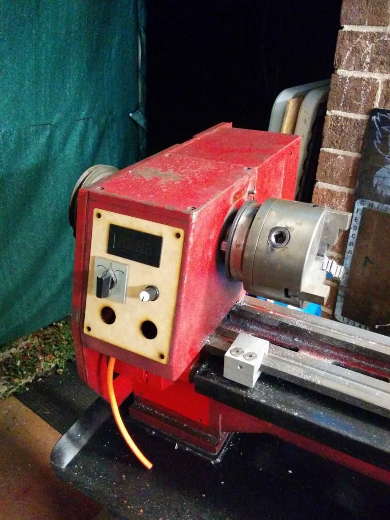
C6 VFD conversion
Here's something that might be of interest to some given there are a few c6 lathes kicking about. Fed up with the constant V belt slip ruining carbide inserts and the dodge-o-rama timing belt getting chewed up and making the slowest 3 speeds useless... To fix this the plan is to put a 3x more powerful motor in with a VFD to allow variable speed and a possible CNC conversion.
The conversion is going to be done in 2 stages. The first is to just throw it together roughly enough to make it work, where I can then machine the rest of the parts to finish everything 100%. Then the next stage will be to tidy up the installation, wiring etc.
Decided to go with a 1.5hp dual voltage 3 phase motor off ebay to replace the gutless 0.5hp single phase offering it came with. This is the place i got it from but they don't seem to sell them anymore.
http://stores.ebay.com.au/cononmotor/Three-phase-Motor-415v-/_i.html?_fsub=5221176018
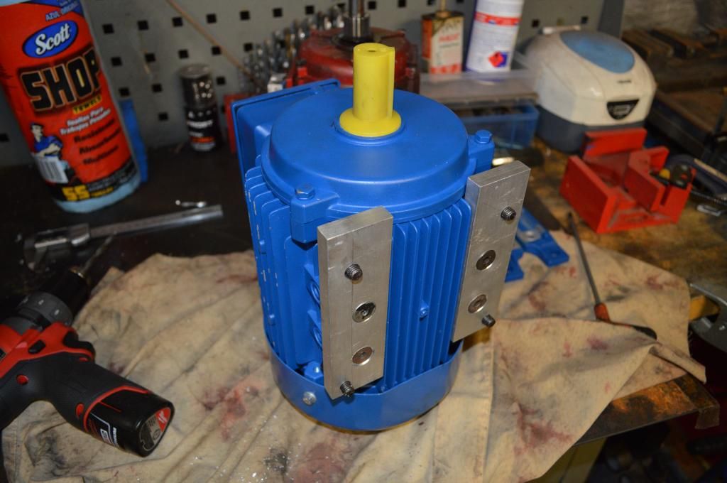
Appears to be a common enough motor to obtain though. The type is "YX3-80M2-2BJ". This new motor is much bigger and needs quite a bit of butchering to make it fit in. But fit it does 
Anyone that's tried to remove the stock motor knows it is the biggest nightmare if the lathe is still bolted down to the stand. The two bolts beneath the motor are basically inaccessible and take ages to remove!
To fix that, two strips of 50mmx10mm flat bar get drilled to bolt to the motor and another 4x holes to bolt to the lathe, two of them are in a different position. I will ammend this post with the drawing for anyone that wants to do the swap the same way
Next one has to drill a pair of new holes in the lathe itself. Don't worry too much about doing it by hand, every hole on every chinese machine is done that way haha.
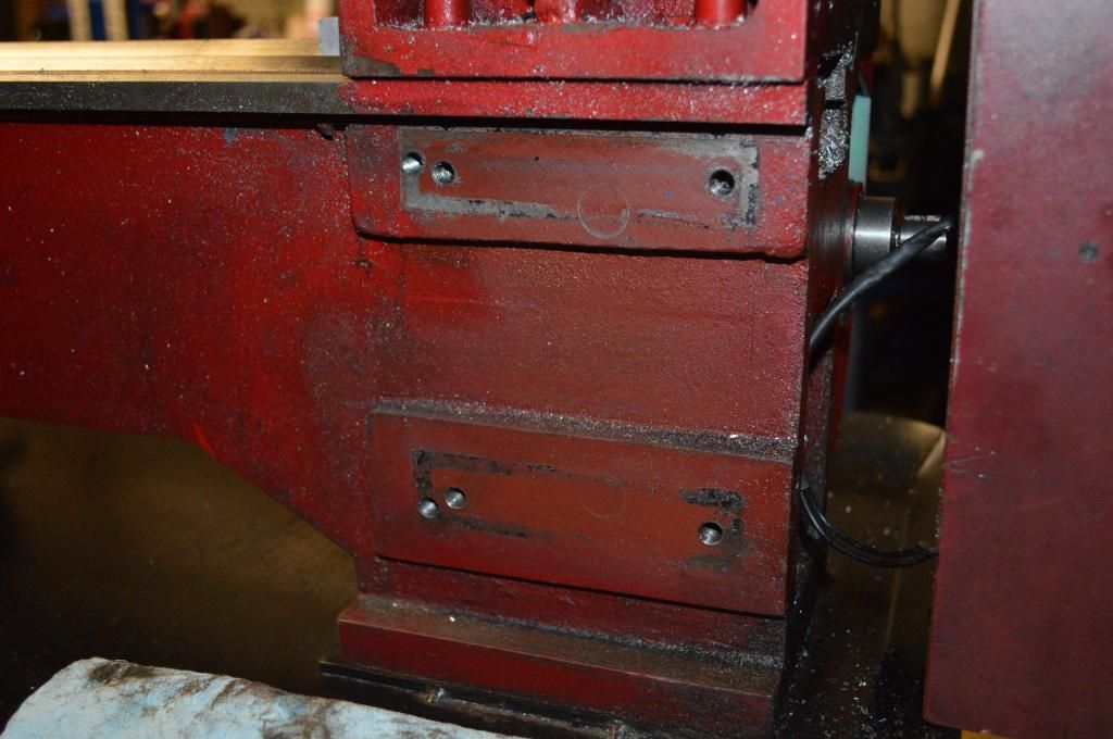
The size and cooling fins on the new motor don't permit the use of the old set of holes to the left of the picture, thus the new ones which, as stated previously, allow them to be done up much easier. The top ones are tapped, the bottom two are through holes with a thread in the aluminium motor mount, they get done up via the gap between the lathe bed. Much easier to install!
All bolted up:
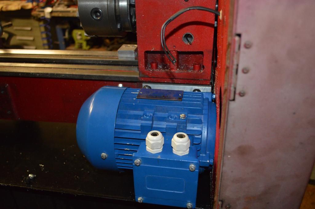
Annoyingly the bolts holding the motor together are 60 degrees off, requiring much drilling and chopping. I'll dremel them to a much nicer finish when i complete the rest of the install.
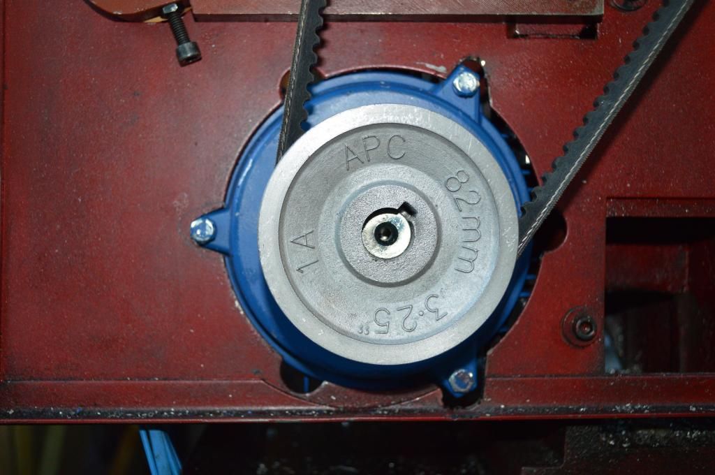
Pressed a cheap cast pulley on for the time being and ran the stock V belt and stock tensioner. Works well.
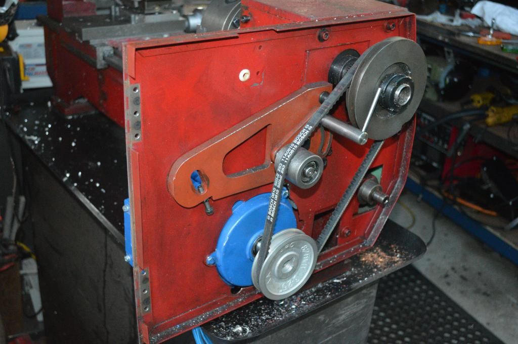
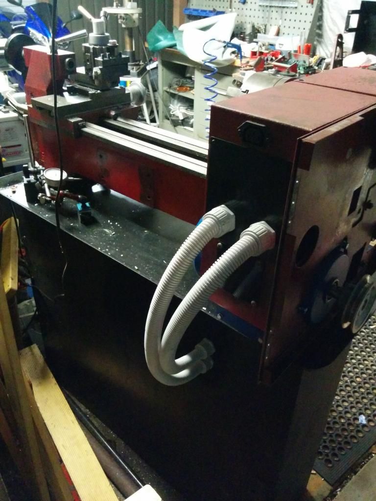
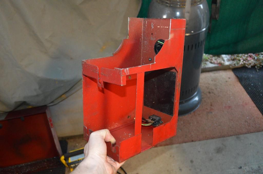
If the back piece is to be kept then it needs chopping as well to clear the motor. Two of the bolts on the motor termination box have to be replaced with countersunks to clear this piece too. It isn't really neccessary as it's just to hide the stock wiring which is no longer there, but it should stop swarf getting over the motor and i like to put tools up on it 
Here's a vid of the first run when it uploads. Much power!
https://www.youtube.com/watch?v=AbawPFWXEsU&feature=youtu.be
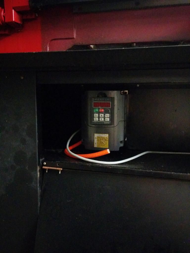
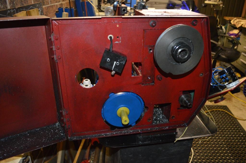
Next I need to mount the vfd into the cabinet, complete the proper, safe wiring of the lot and remake the control panel to incorporate the new controls as well as a Tachometer readout. Also have to hunt down the proper timing belts and pulleys. Then i will be a very happy boy! 
_________________
www.demon50s.com - Minimoto parts
http://www.youtube.com/user/HyzerGlen - Videoooozzz
|
 Sat Dec 20, 2014 8:15 pm
 |
|
|
|
|
|
|
|
|
|
|
|
|
|
|
|
|
|
|
|
|
|
|
|
|
|
|
|
|
|
|

 RoboWars Australia Forum Index
-> Technical Chat
RoboWars Australia Forum Index
-> Technical Chat