|
|
Rotwang
Experienced Roboteer

Joined: 15 Jun 2004
Posts: 1589
Location: Vic


|
This post follows on to a question I posed in the BotBiz thread, rather than continue the conversation there cluttering that thread it’s probably better here. Aaron Andrew Nick and Marto replied, thanks for that.
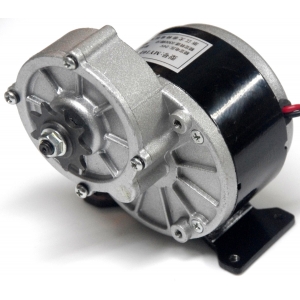
The story so far is that I have 2 bots using the 250watt geared rare earth motors for drives one as a spinner without gearbox and another as a hammer.
The hammer welded relay contacts initially the big jaycar ones worked with some diodes to help.
The spinner with a SSR and no reversing is no problem
.
Bane one and Maestro between them have damaged 1 Sidewinder 1 Roboteq and something like 5 IBC’s, Scorpions just crash and work after a reboot.
As far as I can tell no one else has tried them as drives, Aaron suggested it as an alternative to winches using the version with the hotter wind.
I have Bane 1 driving using a pair of these
http://www.ebay.com.au/itm/320A-7-2V-16V-Bidirectional-Brushed-ESC-Speed-Controller-RC-Car-Truck-Boat-HP-/141607541668?hash=item20f8779ba4
Cheap and so far totally reliable but I wouldn’t want to be in a real fight though.
The other reason for using this thread is it has this post,
Ian Mc Donald Advanced RoboteerUsername: Team_irelandPost Number: 434Registered: 11-2003 Posted on Friday, September 24, 2004 - 8:53 pm:
Hi Having heard a few stories about Perm motors "Technobot Power Drive motors" buring out Roboteq's due to them causing huge voltage spikes when sudden reverse is used. I was reading through the vantec website purely by chance and found this: " In this situation the batteries act as a voltage clamp protecting the controller. The battery chemistry must be healthy for this to occur. Don't add a series diode in line in the battery line because it will block the clamping action and the controller will fail. Some users place a large 100,000 ufd "computer" electolytic capacitor across the power going into the controller, a good idea, to further smooth the input voltage and clamping action." Could this work with the roboteq's and possibly stop the problem? Any idea's? Regards Ian
Mike Lambert Intermediate RoboteerUsername: GrafixPost Number: 225Registered: 10-2003 Posted on Friday, September 24, 2004 - 10:15 pm:
no.
Stefan Member RoboteerUsername: BugsPost Number: 99Registered: 10-2003 Posted on Saturday, September 25, 2004 - 2:55 am:
No, as in: it won't stop the problem.
Paul Cooper Intermediate RoboteerUsername: _m2Post Number: 175Registered: 10-2003 Posted on Saturday, September 25, 2004 - 3:10 pm:
Roboteq and Technobots are still working to find a robust solution to this problem, a problem which we now understand. The voltage spike aspect has been resolved but the curent spike is being worked on. To give you some idea, we estimate a current spike in excess of 2200A being generated by the Power Drive motor in regen. Two solutions exist, either cope with this current or reduce the current. Once we have a proven solution, the Roboteq will take some beating in the world of DC speed controllers. Paul
Mike Lambert Intermediate RoboteerUsername: GrafixPost Number: 231Registered: 10-2003 Posted on Sunday, September 26, 2004 - 9:49 pm:
See, ask a question and you shall get a good and honest answer from the man himself. Mike.
Kane Aston Member RoboteerUsername: KanePost Number: 58Registered: 10-2003 Posted on Monday, September 27, 2004 - 9:59 am:
The Roboteq already takes some beating in the world of DC speed controllers!
Stefan Intermediate RoboteerUsername: BugsPost Number: 101Registered: 10-2003 Posted on Monday, September 27, 2004 - 10:41 am:
Every pice of technoligy has it's quirks. There's no perfect speed controller, there probably never will be. At least not yet, mine is still on the drawingboard
Craig Danby Intermediate RoboteerUsername: Craig_antoPost Number: 244Registered: 10-2003 Posted on Monday, September 27, 2004 - 12:12 pm:
Tanto can run the power drives 
james baker Advanced RoboteerUsername: JamesbPost Number: 495Registered: 10-2003 Posted on Wednesday, September 29, 2004 - 1:17 pm:
just a suggestion, could a 1 farad power cap from something like a monster car stereo install be used to absorb the backwash of current. These regularly see over 2000A in top installs. not looked into this, just askin
Kane Aston Member RoboteerUsername: KanePost Number: 66Registered: 10-2003 Posted on Thursday, September 30, 2004 - 4:27 pm:
No, well it could. But that wouldn't really fix the problem.
Paul Cooper Intermediate RoboteerUsername: _m2Post Number: 176Registered: 10-2003 Posted on Thursday, September 30, 2004 - 5:10 pm:
James The 2200A current is between the motor and the FETs, putting a cap like this across the motors would just be seen as a short circuit to the controller. Putting it across the battery would not resolve this particular issue. Paul
Craig Danby Intermediate RoboteerUsername: Craig_antoPost Number: 250Registered: 10-2003 Posted on Thursday, September 30, 2004 - 7:53 pm:
Paul if u willing to replace the controller if you blow it up (not that they should) I'm willing to let you try the 48330esc on power drives email me if u interested
Kane Aston Member RoboteerUsername: KanePost Number: 68Registered: 10-2003 Posted on Friday, October 01, 2004 - 8:57 am:
6.3lbs weight!!! 1 channel http://www.teamwhyachi.com/motor.htm That's 5.7Kg of speed controller for drive!
Craig Danby Advanced RoboteerUsername: Craig_antoPost Number: 257Registered: 10-2003 Posted on Friday, October 01, 2004 - 12:48 pm:
yea and? call it an insentive to loose weight
james baker Advanced RoboteerUsername: JamesbPost Number: 499Registered: 10-2003 Posted on Friday, October 01, 2004 - 4:12 pm:
thanks kane/paul, as I said, didn't look into it, just something from the old boyracer days
Knightrous Oxide Advanced RoboteerUsername: TeamvertexPost Number: 543Registered: 01-2004 Posted on Saturday, October 02, 2004 - 1:03 pm:
Maybe a small device that monitors the voltage on the motor wires what will switch the motor leads to a something that will burn up this voltage spike when braking until the voltage drops back to a level that the fets will take and then connects the motor back to the controller? I'm sure it could be done with a picaxe chip and some smart thinking. Just a brainstorm and I'm sure someone will pick holes in the idea.
Stefan Intermediate RoboteerUsername: BugsPost Number: 102Registered: 10-2003 Posted on Saturday, October 02, 2004 - 1:48 pm:
Euhmm.. hey you've got it all figured out I'm sure they'd have a solution if it where an easy fix. I'd try to use a higher switching frequency and a lower duty-cycle on regenerative breaking. But I'm sure they've tried all the easy fixes. Maybe they can't upgrade the cpld contents with the normal firmware upgrade software.
Kane Aston Member RoboteerUsername: KanePost Number: 73Registered: 10-2003 Posted on Saturday, October 02, 2004 - 5:17 pm:
You guys do realise that the maker of the Roboteq is working on this problem to produce a more refined fix!
Paul Cooper Intermediate RoboteerUsername: _m2Post Number: 178Registered: 10-2003 Posted on Saturday, October 02, 2004 - 6:45 pm:
Knightrous, the problem is current spikes rather than voltage. The Roboteq has built in hardware suppression against 'normal' voltage spikes and additional means of isolating the motor from the output stages built into the software. Some spikes from low impedance motors like the LEM and Power Drive have so much energy and are of such short duration that even this protection is not adequate. Fortunately this issue has recently been resolved and works well. The method of dumping regen energy into some switched load has been considered not just by myself but by other speedo designers I could mention and it is far from being a desirable solution. Stefan, it is all about the duty cycle but a lower duty cycle is what is causing the problem at the moment. You need to be able to detect when in regen and also measure the regen curent in the bridge but very few bridge designs appear to allow for this. You are also quite right that the firmware upgrades cannot alter all functions, some are embedded as you suggest in the PLD which includes how the bridge is controlled. We remain optimistic that a solution exists and I certainly do not mind suggestions, you never know it may just prompt a new thought process. Thank you to those who have emailed direct with suggestions. Paul
Paul Cooper Intermediate RoboteerUsername: _m2Post Number: 235Registered: 10-2003 Posted on Friday, January 21, 2005 - 3:31 pm:
Following both successful bench and field trials (thanks to Dantomkia Mike), a new version of the Roboteq is now available - AX2550HR. The development has also led to improvements on the standard version. A new version of the software will be available next week (waiting for me to upload) which will amongst a number of continual developments now feature regen current monitoring. What this means is that the controller will send a minimum of 25% of the regen current back to the batteries until it falls below a fixed threshold. Once it falls below this threshold, the controller will bring the motor to a halt. Effectively this means the deceleration ramps may be paused during periods of high regen current. This is very unlikley to be even noticed with motors such as the Bosch 750W, it's there for LEM's and Perm Power Drives etc. There is also a small hardware mod of 4 diodes to cope with spikes during regen. All motors generate these spikes and the standard Roboteq can cope with these for motors except the disc type LEM's etc. There is a risk that a faulty motor could also generate these spikes. These diodes are fitted to all units shipping from 1 Jan 2005 but can be retro-fitted to previous controllers. Even with these changes, the disc motors (especially the Power Drive) still generate enormous regen currents so a new version is available that has twice the number of output FET's which means is can cope with twice the regen current as well as running cooler. Existing standard controllers can also be upgraded to the HR version. It would be unrealistic to say that the Roboteq is now unbreakable, but surely it must be close. See here for further details. Paul
Kane Aston Intermediate RoboteerUsername: KanePost Number: 123Registered: 10-2003 Posted on Tuesday, January 25, 2005 - 1:26 pm:
Yipee!!!
Mr Stu ModeratorUsername: StuPost Number: 721Registered: 10-2003 Posted on Tuesday, January 25, 2005 - 4:24 pm:
Yeah - go get a Roboteq in Behemoth now Kane, learn how to drive with a good accurate control speed controller - no excuses now - you can't blame the 4QD's for your driving now, hehe. Mr Stu[/quote]
_________________
Satisfaction is proportional to effort and results.
|
 Sun Aug 09, 2015 9:38 am
 |
|
|
Spockie-Tech
Site Admin

Joined: 31 May 2004
Posts: 3160
Location: Melbourne, Australia
|
Wow, thats a wall of text !
Want me to edit it and tidy it up a bit so its more readable ?
Bottom line, they do generate incredible spikes, I recall we looked at them on a scope after Gary fried his 2nd IBC with them.
Detecting the spike and then responding to it is unlikely to work in time with anything except direct-analog circuitry..
a microprocessor will be too slow (unless you're running some nanosecond-response 100mhz+ RISC chip), and even with analog, theres not much I can think of that could switch in fast enough except another FET to try and absorb/redirect the spike. TVS diodes would engage, but with that sort of current spike (Seriously, 2200A ?!), they wouldnt be low enough resistance to prevent the voltage from rising to damaging levels.
Designing a responsive Transient/Surge absorption add on is very difficult when you are PWM'ing a highly reactive coil (motor), since kickbacks are constantly occurring from the pulsing, so distinguishing between a tolerable level of kickback that wont blow the bridge and an unacceptable level requires careful tuning of the absorption mechanism to match the particular characteristics of the motor, and load conditions - Its not like a fuse that can just react when > condition X.
Off the top of my head, I agree that the simplest way would to massively overrate the bridge FETS so they could (hopefully) cope with the surges as part of normal recirculation operation, but this brings a fair bit of additional cost and weight, plus large fet drive issues.
Interesting that those "320 Amps" RC (There's those Hobby Amps again  ) controllers will take it. I wonder where the energy is going with them. ) controllers will take it. I wonder where the energy is going with them.
_________________
Great minds discuss ideas. Average minds discuss events. Small minds discuss people
|
|
Sun Aug 09, 2015 11:08 am |
|
|
|
|
|
|
|
|
|
|
|
|
Spockie-Tech
Site Admin
Joined: 31 May 2004
Posts: 3160
Location: Melbourne, Australia
|
How similar to an IBC in layout can you get ?
Big Caps and motor wires up one end, Fets in the middle, Micro, power and Pins up the other end. same general shape too.
Ok, its an obvious layout, but still. It even looks like its got the switching regulator in there. Change the IBC to surface mount from through hole and thats what it would look like.
Im guessing from the 6 pin D-Paks, that they're IPS (Intelligent Power Switch) Fet Varieties or similar. (edit. I just noticed that most of the legs are solder bridged, maybe they're just normal dumb fets ?) and possible current sensing down the end there near the caps ? (edit, just noticed the trimpot for current adjust). I dont see any TVS diodes there, but if the Fets have auto-shutdown and recovery like IPS's do, they might not be needed.
Has Charles published the schematics ?
Be interesting to see if they can survive the ESC munching Motors
The biggest thing I wish Id done with the IBC is design it to fit in a commonly available enclosure. Those gray cases that Gary found *almost fit were good, but a little annoying to have to massage the board and case to get them in. I wonder if Charles has an enclosure he's based his design around.
_________________
Great minds discuss ideas. Average minds discuss events. Small minds discuss people
|
|
Sun Aug 09, 2015 8:10 pm |
|
|
|
|
|
|
|
|
Spockie-Tech
Site Admin
Joined: 31 May 2004
Posts: 3160
Location: Melbourne, Australia
|
quote:
Originally posted by Rotwang:
Is anyone interested in trying to fix an AX 2550 Roboteq
Just saw this.. I could have a look, but I probably wont have the same parts they use in stock. might take some shopping to get them. And theres no tech info available on it I imagine. looking at the datasheet, its likely to be a complex box, with programmable current limiting, datalogging, and all sorts of stuff..
Still, if its just the Bridge thats fried, as long as the spikes didnt get back up into the gate drive circuitry, it might be repairable. Have you looked at the board to see if the Fets have combusted and damaged the PCB ?
_________________
Great minds discuss ideas. Average minds discuss events. Small minds discuss people
|
|
Sun Aug 09, 2015 8:42 pm |
|
|
|
|
|
|
|
|
|

 RoboWars Australia Forum Index
-> Builders Reports
RoboWars Australia Forum Index
-> Builders Reports