|
|
miles&Jules
Experienced Roboteer

Joined: 19 May 2010
Posts: 3973
Location: ipswich QLD


|
Miles & Jules Robots QLD
We have had our first battle at the full metal carnage on the 27th/28th nov 2010
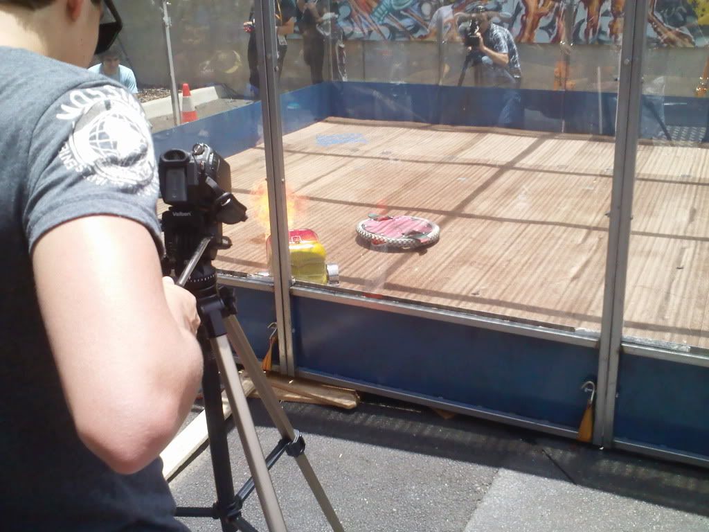
(Pic of lotus vs bodge bot on day 1)
....and we are now addicted!......To wanting to build robots and improve the ones we have already built.
We started thinking about robots after seeing the feather weights at the full metal carnage back in the June at the edge, and we are so glad we went to that battle. Building some robots has been in the back of our minds ever since.
When we found out the next battle was on in November we thought we just wouldn't have the time or the budget to make robots......we are now so glad we did as we had the best experience ever! we started building early November and began rapidly piecing components together with only a few weeks to go.
And thanks to this forum! We had plenty of info from you guys. See our beginners
topic ..thanks! http://robowars.org/forum/viewtopic.php?t=1505
The hardest thing for us was trying to understand how everything worked together. We don't have much radio control experience, but we had built puppets and a had done bit of animatronics for film work. We had played with radio control gear to the point of making puppets eyes blink etc. but we had no Idea about speed controllers or lipo batteries. And no experiance in driving!
So we studied the awesome Drill hacking guide on the robowars wiki
http://www.robowars.org/wikka/DrillHacking101
and also asked you guys on the forum heaps of questions and finally got the drills working. (Those grubs screws are ingenious) At this stage we had the wires from the empty drill triggers running to the drills mounted on a wooden frame via 3m of wire. Very lame but it worked. Notice the screws holding the motors in position.
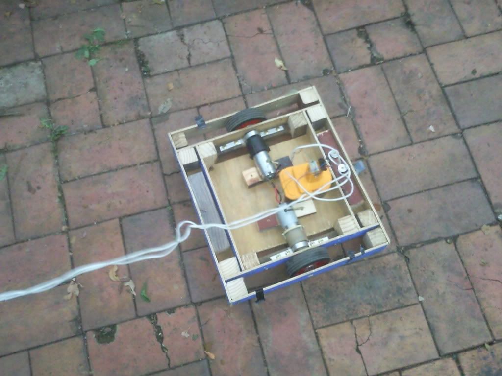
This at least showed us the principle of steering a robot via drills. We didn't buy any new drills for these robots, when the batteries die on the cheap drills we just keep the drill body in a junk box. We had 2 of these powering our super8 and 16mm projectors.(we transfer super8 and 16mm to dvd for people) the other one we had mounted on our camera jib arm, that we use for our animation. So we robbed all of these and had 1 other drill donated from family and found another at the markets for $5. So we had 5 drill motors.
This inspired us to go ahead with two separate robots Wombot and Lotus.
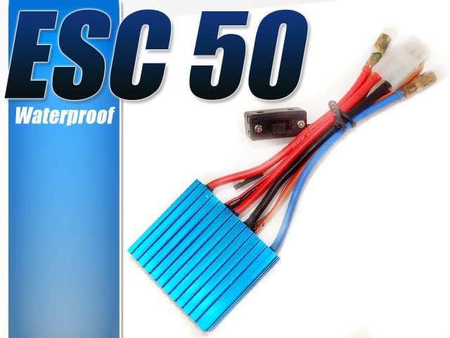
While we were working on their separate designs we still had to work out how the radio receiver could tell these motors to go. So the next thing was tracking down the cheapest speed controllers, to get our robots moving.
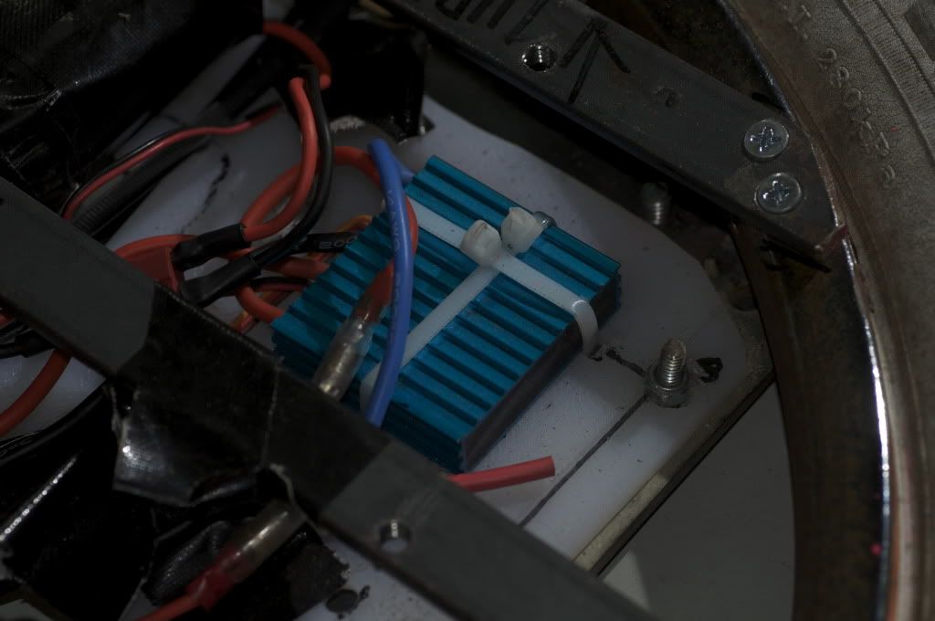
So we bought 4 blue speed controllers from ebay. $25.00 each. Recommended by you guys on the forum as the cheapest way to start moving our robots.
By this time we had 2 weeks left before the 27th. So we were hoping they would arrive in time for us to try and make them work. We were starting to panic about
receivers and transmitters as we were short on funds and time.
We had a spectrum 5 channel transmitter already but no reciever. So rather than risk buying a reciever for it and it not work, we sold that on ebay, which funded our battery charger.
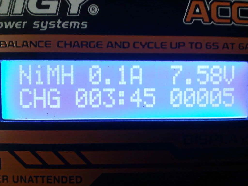
http://www.hobbyking.com/hobbyking/store/uh_viewItem.asp?idProduct=7028&Product_Name=Turnigy_Accucel-6_50W_6A_Balancer/Charger_w/_accessories&aff=109259
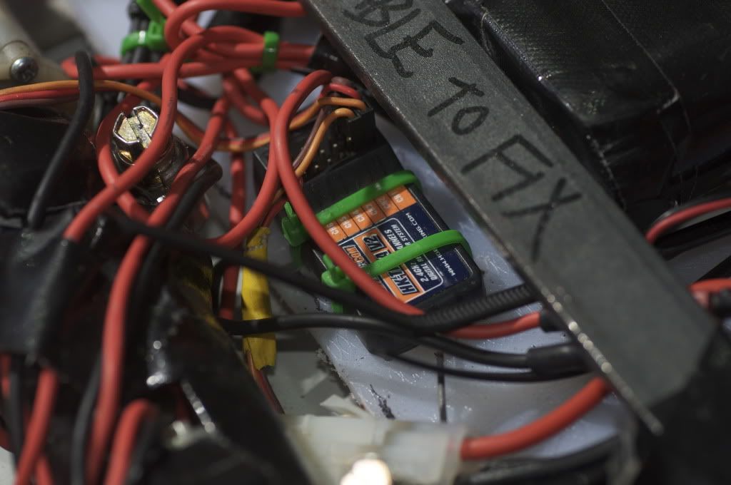
We didn't think we had time to order them from hobby king. So we got two sets of 6 channel hobby king radios from Steve. Thanks Steve!
We had old lithium battery packs from rc cars. 2x 9.5v, a 8.4 and a 7.2v.
We had to work with these right up until the 26th when our new charger arrived from hobby king. We had bought 10x a123s from Steve the week before, but didn't think our charger would arrive before the 27th so we didn't solder together a a123battery pack until the last minute. On the early hours of the 27th we soldered together 5 cells, taped it up and then Don showed us how to work out the menus on the charger at the event .Thanks Don!
So then Glen suggested that the 5 x a123cells might be too much voltage for the 12volt blue speed controllers. Thanks Glen! We didnt want to fry our only speed controllers. So for day one of the event ,we used the other lithium rc batteries that we already had. They were waaaaaay slower though. But we didnt know this until day 2.
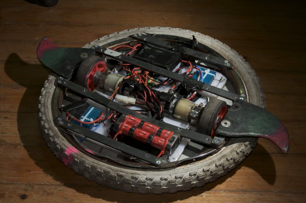
So that night we de-soldered one of the a123 cells to make it a 4pack. Then created another 4 cell battery pack. So now we had a proper charger and a123 battery packs for each of our robots.
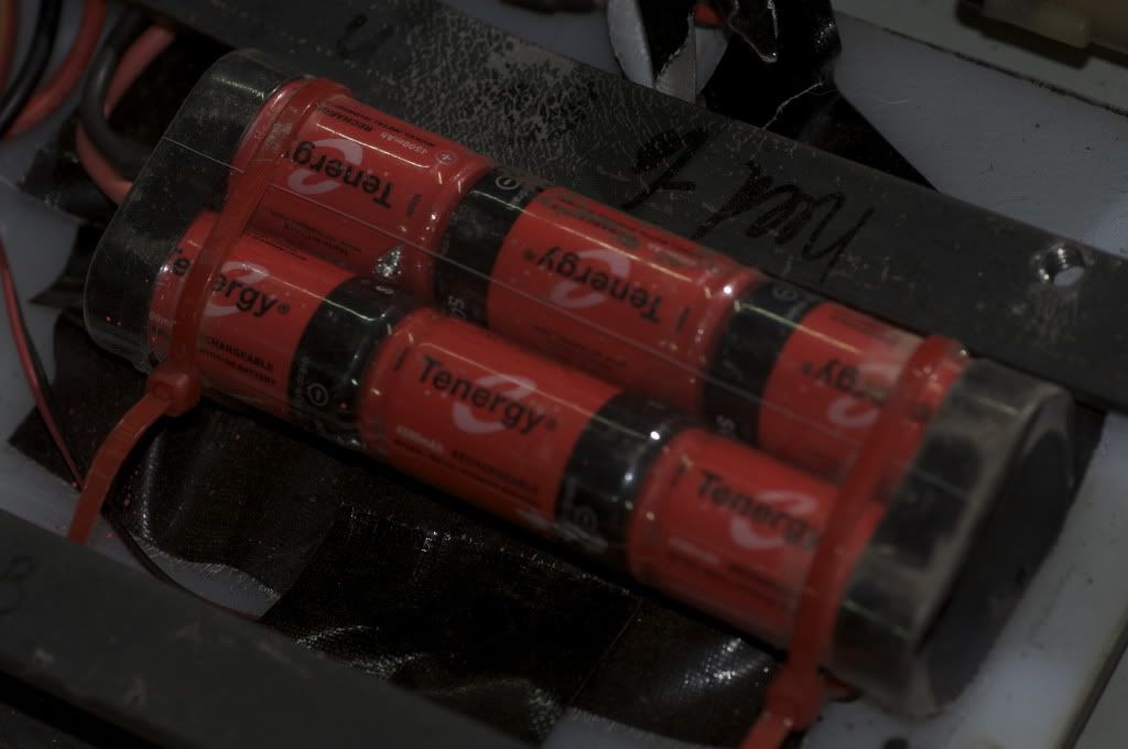
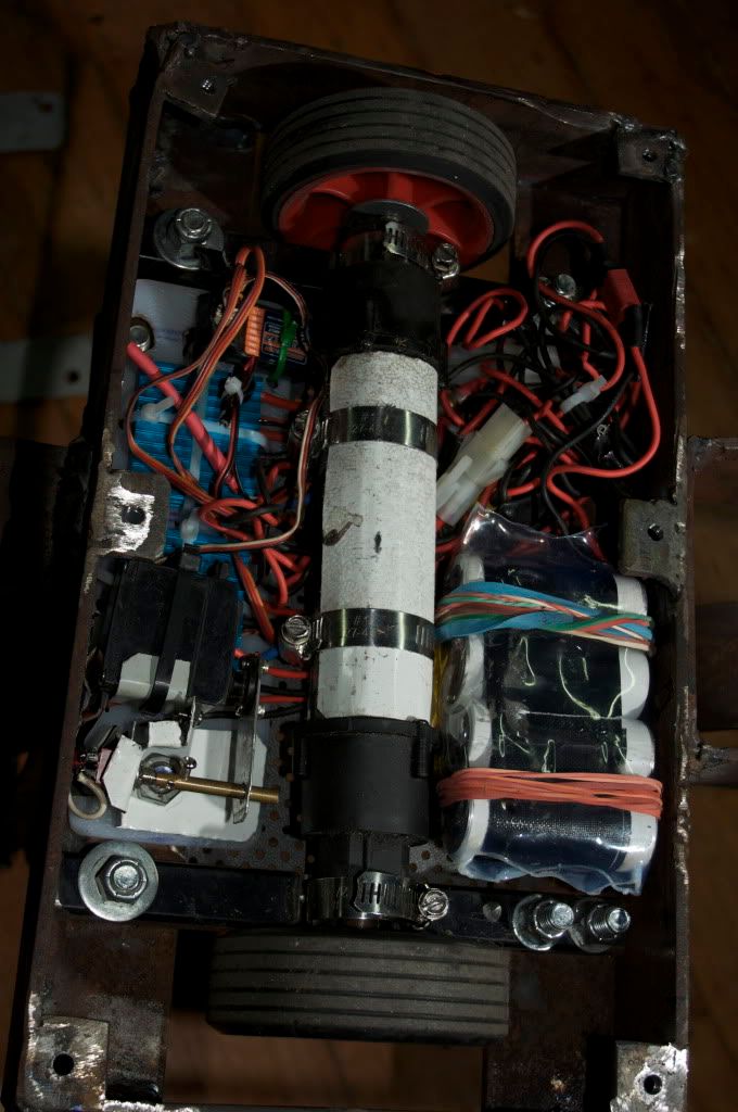
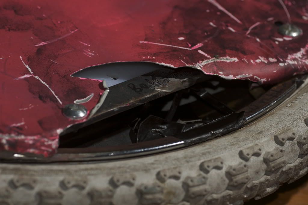
This pic shows the heat shrunk coke bottle covered a123 battery pack.(thanks Aaron for that technique!) Also you can see my servo switching lifter switch. It amazing never let me down,and is still working! That servo is probably 20 years old. You can see in the pic below the damage from Scissorhands on the top edge.It really bent the hell out of the front lifting arm and snapped one of the nose bars off to.(never got a photo of that though.
Going back a bit .
Wombot
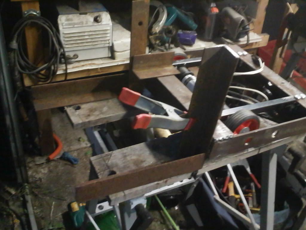
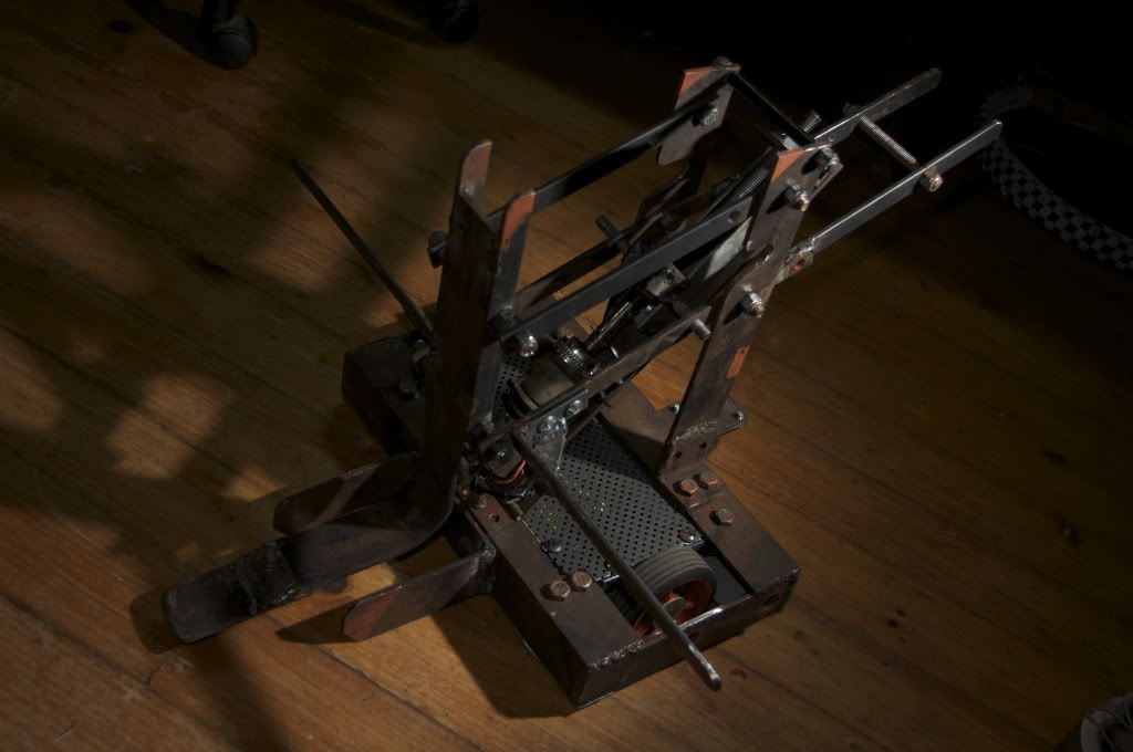
This was before Wombot was a (camera style jib-arm)lifter. It was just going to lift other robots on top of itself. But what happened was it ended up lifting itself up rather than the other robot. So then we went for the jib arm design which puts the weight on its front bars and wheels.
[img]http://i1091.photobucket.com/albums/i396/milesandjules/_DSC1704.jpg[/img
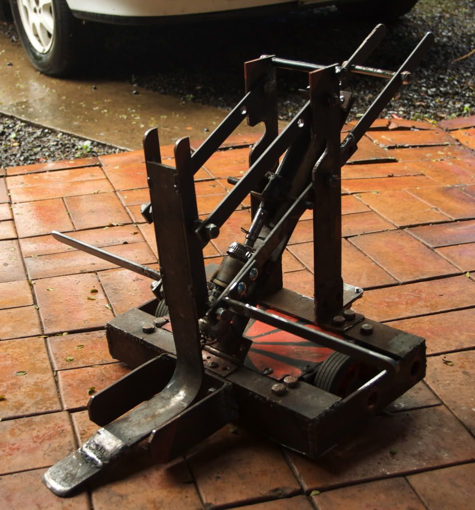
Here is Wombot a day or so after the event with his new side self right bars and new painted top plate(it was white before). I thought it didn't really suite having colours on him so changed it to some heavier grey mesh. Which do you think looks better?
]
It can now actually lift things. Also the wires running to the lifting motor got totally melted by Bodge Bot. I didnt realize this till I removed the top plate and the insulation just crumbled. That was cause of some strange loss of control on Wombots behalf. You can see it happening in this vid.
http://www.youtube.com/watch?v=HPipG7ML0ds
i am currently trying to get Wombot's self righting mechanism working. It could lift itself up from laying on its back, but not sidewards. Now with the bars on the front it can lift itself up from the sides and front and back. But now I need something for the back corner. I think just another two bars at the back should do it. But its already !kg over weight. Will see what will happen with that. Miles
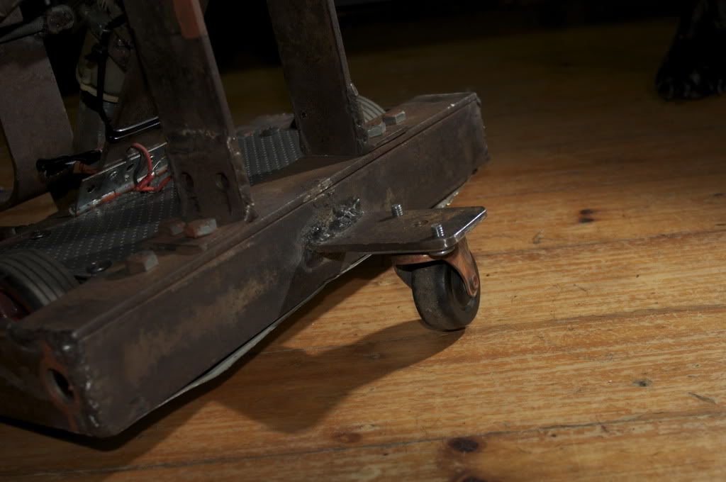
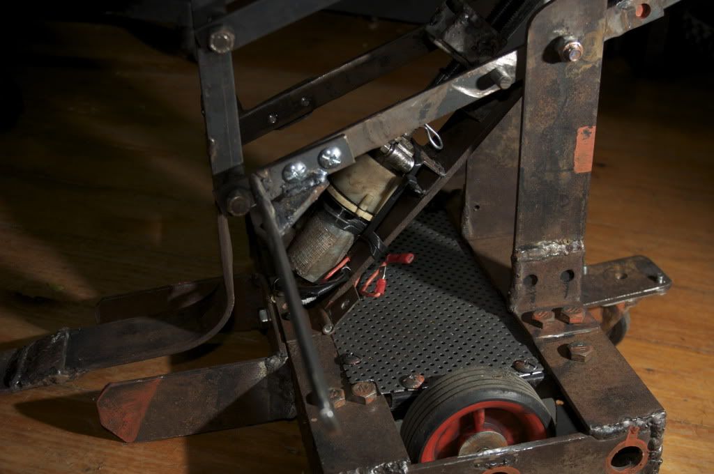
Here is the new wheel added. That stops the front of the robot from lifting up to high as it moves forward. This helps steering to. and keeps the lifter low.Suggested by Jaemus. thanks. Works way better, but probably needs to be reinforced with a triangle of piece of steel.
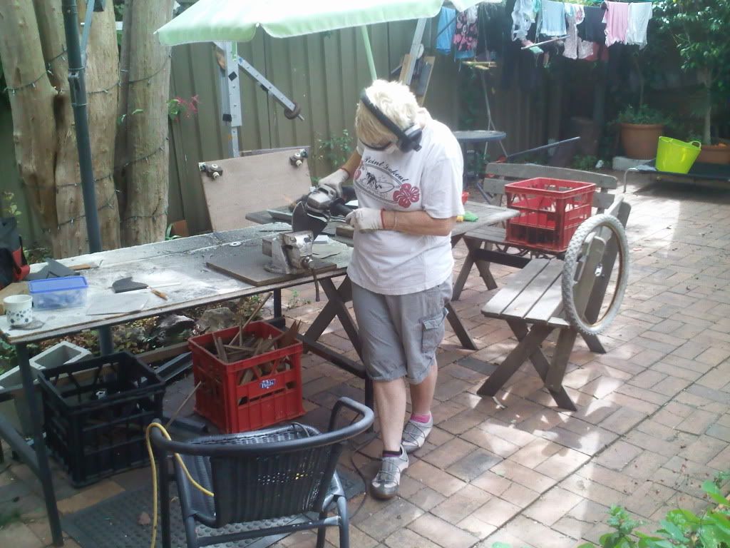
Jules grinding her 10mm bbq plate fins. Lotus tyre waiting on the chair. You can see our filming jib-arm in the background. There is also our bike chain/disco ball motor driven slow turning camera mount leaning against the clothes line. We had to rob parts off both of these for our robots.
Lotus
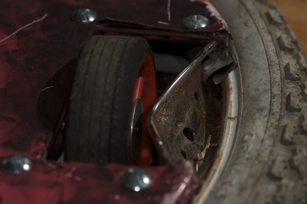
I liked the idea of a spinner and tried to keep my first robot simple. For some reason my first designs were always based around a bike wheel with tyre. I was sort of approaching it like a sculpture using what I could find around the place to make. Once I found the 20” bike wheel I soon realized I would not be able to fit all the gear inside with the spokes and had to remove these which in some ways defeated the purpose of its strength. We had plenty of 5mmX20mm flat bar around so I used that to strengthen inside and to make a frame for the gear to sit on. Unfortunately, and I should have thought of this, you can’t weld onto a bike rim.(not with our welder anyway) So I had to screw the frame etc into the rim and used nylock nuts hoping they would keep it tight.
I wanted heavy metal for its fins hoping it would spin faster by centrifugal force a bit like a flywheel. So I cut through 10mm thick BBQ plate and ground them down to the shape I wanted. These were then tapped and countersunk with 5/8th set cap screws one on either side over the wheels.
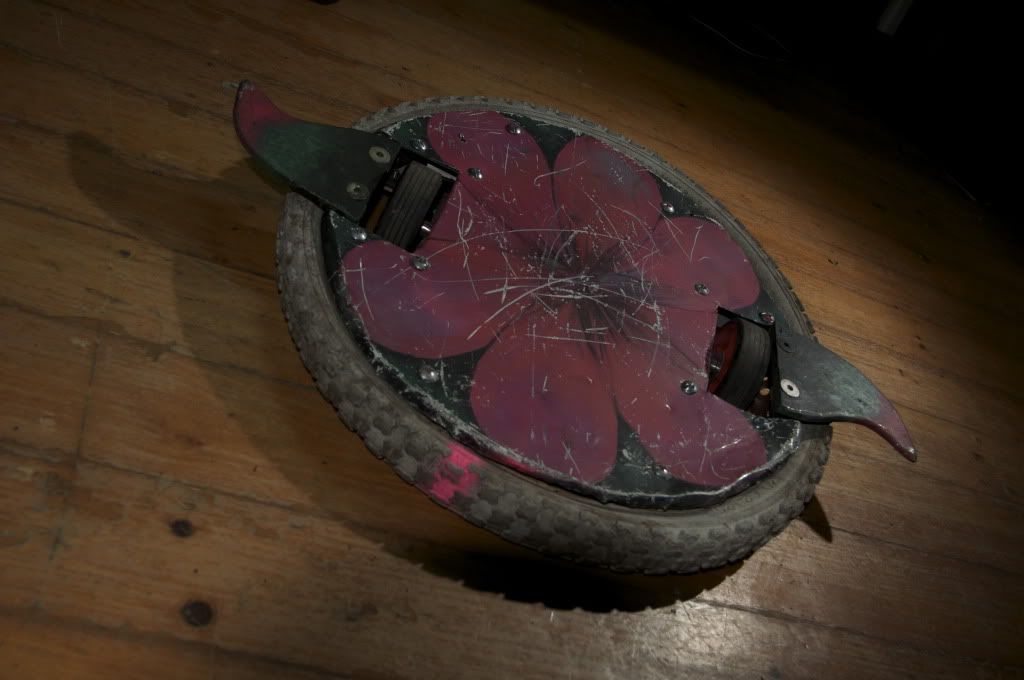
When I started to work on the outer skin, which I cut out of zinc plated tin sheets, I thought it was starting to look like something else like a big water lilly or something sitting in a pond, this was when Baldrick became a Lotus.
I knew there were a lot of faults in this design and we both knew our driving skills were pretty bad but we just wanted to give this a go.
The event Full Metal Carnage at the Edge was for me personally one of the best experiences and I am so glad that we threw out the money worries and the guilt of not animating daily and just did it!
How cool it would be to have one of these every weekend!
I thought all the guys we met throughout the weekend were really helpful and awesome people to meet and how cool to have the chance to fight some of the best Robots in Australia and is it wrong to be proud of my not very well earnt battle scars!
outcome
I learnt a lot, a whole lot. Like about strength and the importance of a good design
I learnt about good batteries, good speed controllers, and how important the motors are to have the speed.
I learnt that you need to have the skills and a whole lot of practice in driving.
Now with that said I want to come back with a better improved Lotus so I can actually do BATTLE!
I realize Lotus at the moment, like it is, is pretty useless. I could get the speed up and try and weld up a stronger support and make a new weapon, but I think the bike rim is my weak point. I still like the round idea with the tyre but also like the idea of a rammer and a spinner that is also flipable. I have been working on several new designs and will put some of these up soon…. Thanks for the awesome weekend - jules.
Scissorhands damage 
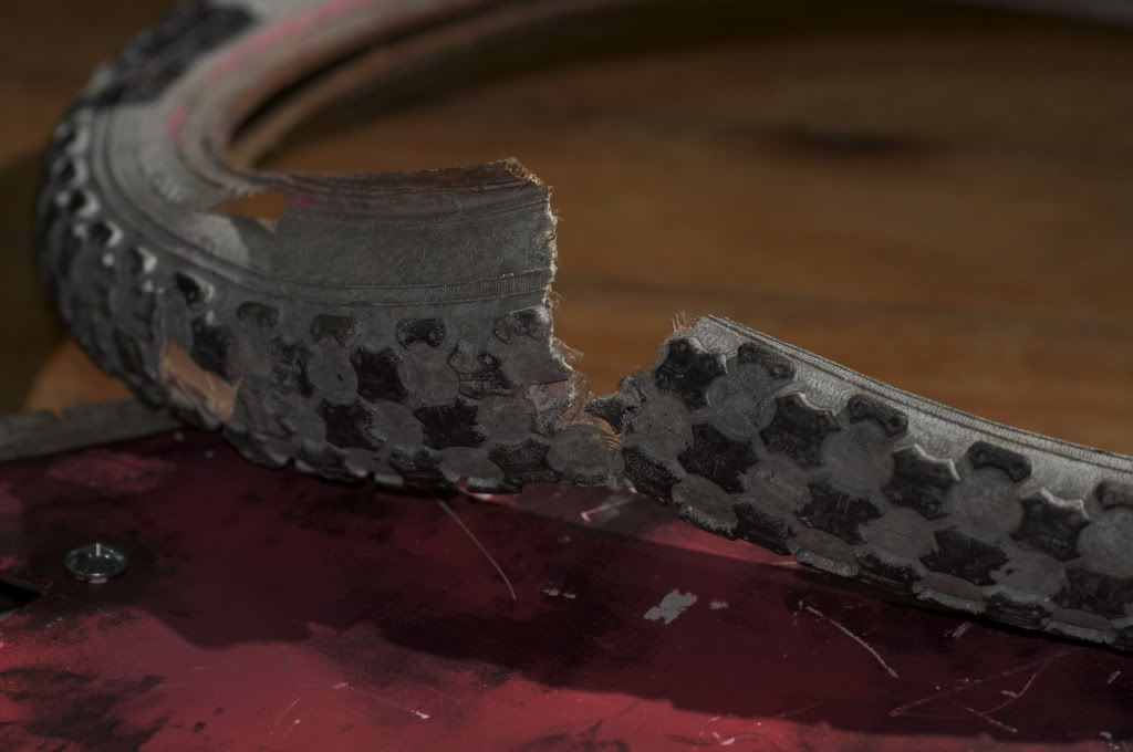
Demon damage
Warning damage
_________________
Miles Blow - Julie Pitts
www.mulesfilm.com.au
www.wombokforest.com.au
-Pickasso- Vivid Sportsman champion 2015
|
 Sun Dec 05, 2010 9:41 pm
 |
|
|
|
|
|
|
|
|
|
|
|
|
|
|
|
|
|
|
|
|
|
|
|
|
|
|
|
|
|
|

 RoboWars Australia Forum Index
-> Builders Reports
RoboWars Australia Forum Index
-> Builders Reports

 [/img]