www.robowars.org

RoboWars Australia Forum Index -> General Chatter

CAD models
Goto page Previous  1, 2, 3 ... 12, 13, 14, 15, 16  Next

Post new topic   Reply to topic
  Author    Thread
Glen
Experienced Roboteer


Joined: 16 Jun 2004
Posts: 9481
Location: Where you least expect


 Reply with quote  

if you export it in IGES you can replicate it quick smart in rhino.

Post Sat Apr 11, 2009 10:16 pm 
 View user's profile Send private message Send e-mail Visit poster's website MSN Messenger
marto
Experienced Roboteer


Joined: 08 Jul 2004
Posts: 5459
Location: Brisbane, QLD


 Reply with quote  

http://dl.getdropbox.com/u/815267/Robot%20Parts/Andrew%20Mod.IGS

http://dl.getdropbox.com/u/815267/Robot%20Parts/Sabertooth%2025.IGS

http://dl.getdropbox.com/u/815267/Robot%20Parts/Sabertooth%2025.IGS
_________________
Steven Martin
Twisted Constructions
http://www.botbitz.com

Post Sat Apr 11, 2009 10:24 pm 
 View user's profile Send private message Send e-mail MSN Messenger
shreddy


Joined: 09 Jan 2009
Posts: 518
Location: Wantirna, Melbourne


 Reply with quote  

thanks
_________________
http://au.youtube.com/user/crustydemonsully

The day I stop giving 100%, is the day I stop competing

Post Sat Apr 11, 2009 11:09 pm 
 View user's profile Send private message Send e-mail MSN Messenger
Glen
Experienced Roboteer


Joined: 16 Jun 2004
Posts: 9481
Location: Where you least expect


 Reply with quote  

could someone go through a quick (if possible Laughing ) guide on how to knock something like this up in solidworks with screenshots? next to every guide on the internet is for making stupid bosses and other infinitely basic parts.

can make most things now but dont even know where to start with angled panels in assmebly

http://img.photobucket.com/albums/v357/Cobrarobotics/backangle.jpg

Sad
_________________
www.demon50s.com - Minimoto parts
http://www.youtube.com/user/HyzerGlen - Videoooozzz

Post Sun May 17, 2009 3:05 pm 
 View user's profile Send private message Send e-mail Visit poster's website MSN Messenger
mark_m


Joined: 23 Apr 2005
Posts: 23
Location: Cambridge, uk


 Reply with quote  
angled panels in solidworks

Assuming you want to make the panels individually, then assemble them:

Extrude the plan view of each panel (basic boss) in a seperate part file. Add chamfers with angle and distances specified to each edge as required.

To assemble them, insert them both into an assemble file, select the faces you want to mate, select mate (paperclip) then choose coincedent. Do the same with the mating corners.

That's how I'd do it, much harder than Rhino but easier to produce drawings for each part. I find it really hard to tune the chamfer angles to get the parts to line up correctly.
If that sounds like thet way you want to do it I can post some screenshots when I get to work tomorrow.

If you've got the sheetmetal module it's much quicker but more difficult to get started.

Mark

Post Mon May 18, 2009 5:03 am 
 View user's profile Send private message Send e-mail Visit poster's website
Glen
Experienced Roboteer


Joined: 16 Jun 2004
Posts: 9481
Location: Where you least expect


 Reply with quote  

i got it to work to some degree but working out what angle the chamfers needed to be and coincident mating them but it takes forevvvvvvvvvvvvvverrrrrrr. youd be there for days building a basic wedge Shocked

if your still floating around on the forums Trent got any advice? http://i41.photobucket.com/albums/e275/trentellis/cadpic.jpg thats pretty well what i want to make angle wise (the shell!)

cheers Smile
_________________
www.demon50s.com - Minimoto parts
http://www.youtube.com/user/HyzerGlen - Videoooozzz

Post Fri May 22, 2009 5:42 pm 
 View user's profile Send private message Send e-mail Visit poster's website MSN Messenger
assassin


Joined: 27 Jun 2004
Posts: 1105
Location: SunshineCoast


 Reply with quote  

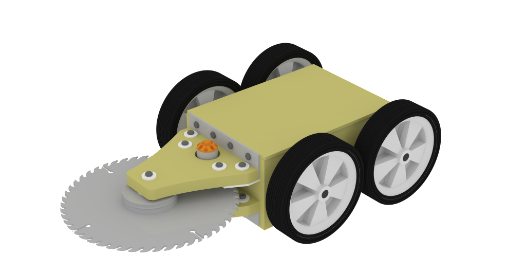
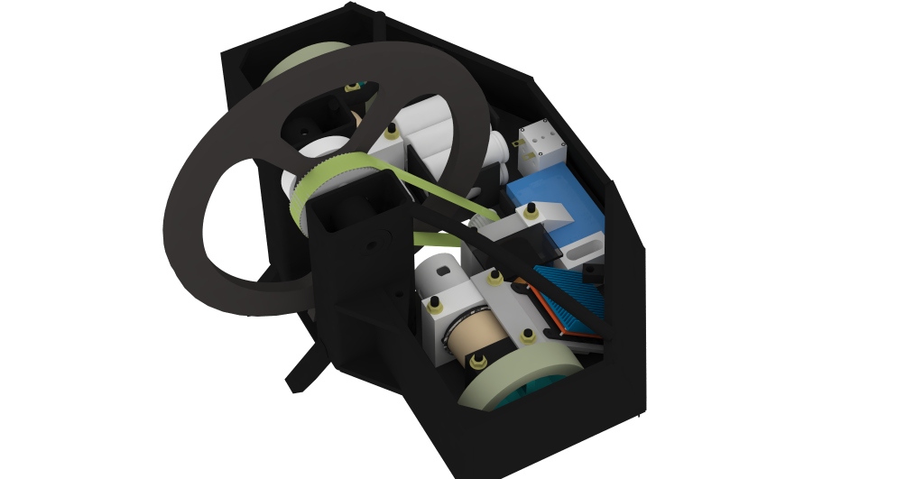
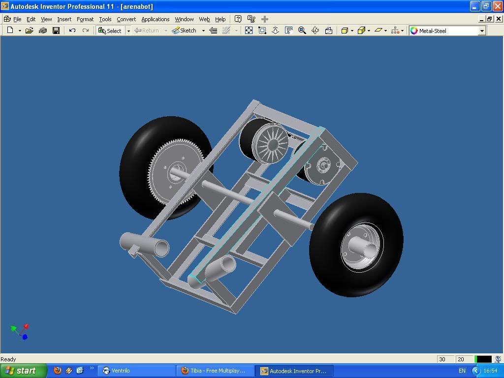
I learnt CAD designing that bot. With that shell and similar designs, I break it down into multiple pieces and then create an assembly. The angle of the edges of the the pieces are not chamfered, there @ right angles(square, 90 degress, normal). Then the corrected edge is mated. Yes, this leaves a gap. But in real life, this is where a have filled the gap with a weld. Also if this mate is to be bent(not welded), the mate is also the correct place to bend the part.

Make sense? Sorry I've been drinking. hehe

But wait I guess theres more... um

To make the correct shapes/dimensions in the first place. Start by creating one part and maybe start measurements/sketches from that part in place for the next. Make sense? View from the top and the side/front, and get the shape correct. Theres lots of ways, which I think is cool and I haven't done enough to get down the best/easiest procedures.

Carve away Very Happy
_________________
Imagination is more important than knowledge. Knowledge is limited. Imagination encircles the world.
Albert Einstein.

Post Fri May 22, 2009 7:10 pm 
 View user's profile Send private message Send e-mail
Glen
Experienced Roboteer


Joined: 16 Jun 2004
Posts: 9481
Location: Where you least expect


 Reply with quote  

just got rhino 4.0 and V ray rendering happening. its a huge improvement over 2.0 and the stock renderer. still plenty to learn on it but heres a sampling Smile

still using the stock 2.0 rhino colours so it should look pretty damn good once i get the v ray textures happening!


plenty of good solidworks features are integrated this time. so i dont have to convert anymore Laughing

worth a try!
_________________
www.demon50s.com - Minimoto parts
http://www.youtube.com/user/HyzerGlen - Videoooozzz

Post Sat Jul 04, 2009 11:56 pm 
 View user's profile Send private message Send e-mail Visit poster's website MSN Messenger
Knightrous
Site Admin


Joined: 15 Jun 2004
Posts: 8511
Location: NSW


 Reply with quote  

I got bored Rolling Eyes


Thought I'd fiddle around with SW and see how hard it was to design some extractors for my car. Working on getting them all tune length now Cool
_________________
https://www.halfdonethings.com/

Post Wed Aug 12, 2009 11:51 pm 
 View user's profile Send private message
Spockie-Tech
Site Admin


Joined: 31 May 2004
Posts: 3160
Location: Melbourne, Australia


 Reply with quote  

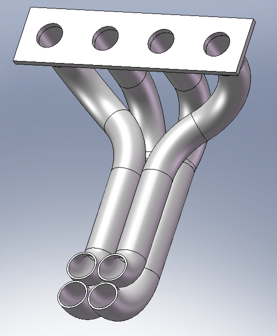
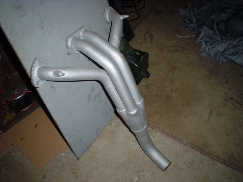
Equal length extractors are supposedly old hat these days.. The trick is getting equal *flow*.

If a front pipe is smooth, but the rear pipe has 4 bends in it to make it equal length, chances are the gas flow speeds will put the pulses out of sync.

plus, afaik, equal length pipes only work effectively over a narrow rpm range where the pulses all arrive at the collector at the right time to create a (relative) vacuum in the next pipe/cylinder to exhaust.

Supposedly for a wider, less peaky power band more suited to wide rpm street use, the Tri-Y design is better than equal length. Equal length is a Nascar thing where the RPM's stay fairly constant for most of the time.

Of course if you're going to hang a muffler on the back anyway, most of the tuned effect is lost in the restriction, but every little bit helps, and pipes look funky Smile

Nice Cad though Smile
_________________
Great minds discuss ideas. Average minds discuss events. Small minds discuss people

Post Thu Aug 13, 2009 2:24 am 
 View user's profile Send private message Send e-mail Visit poster's website MSN Messenger
Knightrous
Site Admin


Joined: 15 Jun 2004
Posts: 8511
Location: NSW


 Reply with quote  

I was thinking why people talk about equal length and not about flow matching (Considering they try to get the head to flow the same in each cylinder before looking into sequential injection and ignition), but I've never read into the subject deep enough. At the moment this is more of a CAD learning thing while preparing myself for a possible project in the future.

Once I get them close to tuned length, I'll start learning to flow test them in FloWorks and adjust the design future. Damn time consuming though, I spent 3 hours after I posted those pictures working on getting the lengths withing 60mm of each other Shocked [Shortest being 535mm and the longest being 595mm]
_________________
https://www.halfdonethings.com/

Post Thu Aug 13, 2009 8:34 am 
 View user's profile Send private message
Spockie-Tech
Site Admin


Joined: 31 May 2004
Posts: 3160
Location: Melbourne, Australia


 Reply with quote  

Of course the next trick after you get your perfect design done is to actually make it fit in the car around all the accessories, mounts, starters etc. which usually ends up trashing your nice design when it collides with reality. Sad

A guy down here used to be "the man" to go to for custom made racecar pipes.. Shane Cable. I reckon at one stage about 1/3 of the Vic Drag Cars had a "Pipes by Cable" sign on them somewhere..

He had done so many over time that he could visualise them, and actually build them *in the car*. He would buy a big box of pre-made short mandrel-bent "U" segments, and would just chop the U's at whatever angle the next bend needed, then Tig that segment in place.

Result - perfect fit pipes to suit the car, and the word was they always made good power because he just instinctively knew how to get the pipes running equal flow without any fancy CAD simulations purely because hed been making them for 20 years.

Its amazing to see how much technology allows us to "rediscover" what craftsmen learned in the past through experience.
_________________
Great minds discuss ideas. Average minds discuss events. Small minds discuss people

Post Thu Aug 13, 2009 11:13 am 
 View user's profile Send private message Send e-mail Visit poster's website MSN Messenger
Glen
Experienced Roboteer


Joined: 16 Jun 2004
Posts: 9481
Location: Where you least expect


 Reply with quote  

i dont know how you could build extractors OFF the car unless you had something with an olympic sized swimming pool engine bay ala valiant Laughing

youll have fun doing it in an mr2 ill assure you of that, i just crush bent all the pipes before i killed the bender and sent it over to a friend in WA who put the collector bit and flanges on it for me and thankfully it fitted. gunna use an old gutted kawasaki 1300 slip on i got given as an exhaust. ive seen one done before and it sounds awesome.

heres something for you to dream of Razz


theres arguments for interference exhaust length and tuned length so in my eyes that means it doesnt matter Laughing i think the primary tube diameter is probably the only important thing. thats all i built mine around anyway.

http://autospeed.com/cms/title_Out-the-Exhaust-Part-Three/A_1484/article.html - good article on it.

work out the flat pack shape in sw too so you can hydro form them Laughing
_________________
www.demon50s.com - Minimoto parts
http://www.youtube.com/user/HyzerGlen - Videoooozzz

Post Thu Aug 13, 2009 11:33 am 
 View user's profile Send private message Send e-mail Visit poster's website MSN Messenger
Knightrous
Site Admin


Joined: 15 Jun 2004
Posts: 8511
Location: NSW


 Reply with quote  

I had a set of Tri-Y's for the 16V motor.

The internal joins were pretty shit and the mergers were ass as well. They were suppose to be Genie/Hurricane clones, but seemed to lack the genetic material that provides quality Laughing

Not much room to build extractors in the engine bay of the MR2, but with the motor/gearbox hanging from an engine crane, it certainly helps make things easier. If I could eventually work towards producing something pretty like this:

I'd be pretty happy with myself. The maths and designing is the fun part, eventually producing something that works well is just the icying on the cake Razz
_________________
https://www.halfdonethings.com/

Post Thu Aug 13, 2009 11:54 am 
 View user's profile Send private message
Rob Team Rotwang


Joined: 19 Jun 2004
Posts: 294
Location: Victoria


 Reply with quote  

Just a snapshot of refbots cad model

I plan to come back and do some more detail for the tire treds and fine tune the arm angles but this is 99% what exists of ref boot in real life..

What i found most difficult was angling the pipes at the front, this was the first time i used "3D sketch" in inventor..

my future goal is to get reboot into cad...that robot was clearly not designed in cad lol, but ill give it my best shot to do it in reverse order, i guess cars are modeled first in real and then put into cad so its not the necessarily the wrong way to go about things Laughing


Post Sat Aug 29, 2009 5:01 pm 
 View user's profile Send private message AIM Address MSN Messenger
  Display posts from previous:      

Forum Jump:
Jump to:  

Post new topic   Reply to topic
Page 13 of 16

Goto page Previous  1, 2, 3 ... 12, 13, 14, 15, 16  Next

Forum Rules:
You cannot post new topics in this forum
You cannot reply to topics in this forum
You cannot edit your posts in this forum
You cannot delete your posts in this forum
You cannot vote in polls in this forum


Last Thread | Next Thread  >
Powered by phpBB: © 2001 phpBB Group
millenniumFalcon Template By Vereor.