And I figured that remade with an M2 or M3 screw it'd be nifty.
thoughts?
I have a pcb manufacturer lined up who reckons he can probably make them, (with silk screen, solder mask etc) but it'll wind up costing ~$100 and i'll probably have 50x ant size and beetle size.
Or i can make them on the mill, without anything fancy as one offs.
Does it need some kind of plastic housing? _________________ Mechanical engineers build weapons, civil engineers build targets
Mon Mar 05, 2012 9:33 pm
seanet1310
Joined: 08 Nov 2006
Posts: 1265
Location: Adelaide
plastic housing in an ant would be a waste of weight. a plastic spary or kapton tape would be better to prevent shorts.
Look good and useful, nice and simple to use _________________ Remember to trust me, I am an Engineer.
Down side to those is kinda hard to mount without a PCB though.
I was planning on making some on the mill first but i was after ideas on things like housing and mounting. _________________ Mechanical engineers build weapons, civil engineers build targets
Joined: 16 Jun 2004
Posts: 11802
Location: Sydney, NSW
I'm not seeing why we can't just buy the PCB switches - they look about right for ants. If there were any design changes, I'd vote for a slightly larger PCB and some separate mounting holes. If you were going to get them made, it might be cheaper to go with heavier copper and forget about plated holes, the mask and screen. using thinner PCB might be a useful option too.
BTW: I can get 2mm or 2-56 screws pretty cheaply if you go ahead - I have a box of 2mm x 8 in stock.
Tue Mar 06, 2012 12:07 am
Jaemus Experienced Roboteer
Joined: 01 Apr 2009
Posts: 2674
Location: NSW
no way im epoxying a power switch into a beetle, needs screw mounts _________________ <Patrician|Away> what does your robot do, sam
<bovril> it collects data about the surrounding environment, then discards it and drives into walls
Tue Mar 06, 2012 9:22 am
Nick Experienced Roboteer
Joined: 16 Jun 2004
Posts: 11802
Location: Sydney, NSW
How about this variation on the Aeroconsystems switch for Ant sized bots? Same small screw and soldered-on nut, but this time the underside of the screw does the switching between pads on the same side of the PCB. The two sides of the PCB would look like this:
In the diagram, green is the PCB substrate, orange is copper track and yellow is the nut & screw. The nut is soldered to a pad just to keep it in place, it does not form part of the circut. The side of the PCB with the screw head faces the outside of the bot and the pads on the back of the switch are connected with many small vias that will fill up with solder and provide a low resistance path when wires .
Extend the bare PCB enough to have mounting screw holes and you have a practical switch that can be accessed via a small hole in the bot's frame, with wires soldered to the inside surface.
Tue Mar 06, 2012 10:38 pm
Valen Experienced Roboteer
Joined: 07 Jul 2004
Posts: 4436
Location: Sydney
I figured the aerocon one would be too huge for ants by lots.
the last switch i tried to make for an ant wound up being 5 grams it was just a bolt a nut and some fiberglass so to make this fit into the weight we *really* need to work on keeping it light.
My plan was to keep the overall dimensions to around 10mmx8mm or so or less if it fits.
wrt vias most board places have limits on the number of vias they will do (basically they don't like cutting or drilling, its expensive for them to do)
I do like the whole keep everything on one side arrangement, perhaps with a nylon nut we can then have the back side electrically isolated for free essentially.
My only concerns are getting enough surface area for the current so it doesn't heat up and ensuring the head engages on both tracks (if the bolt is at a bit of an angle it'll only contact one pad) _________________ Mechanical engineers build weapons, civil engineers build targets
Wed Mar 07, 2012 1:06 pm
Nick Experienced Roboteer
Joined: 16 Jun 2004
Posts: 11802
Location: Sydney, NSW
All good points! That drawing has heaps of places to save space; I used an M3 screw with an oversized head but we could go down to a smaller screw. The space around all the pads can be reduced and using a thinner PCB would save weight.
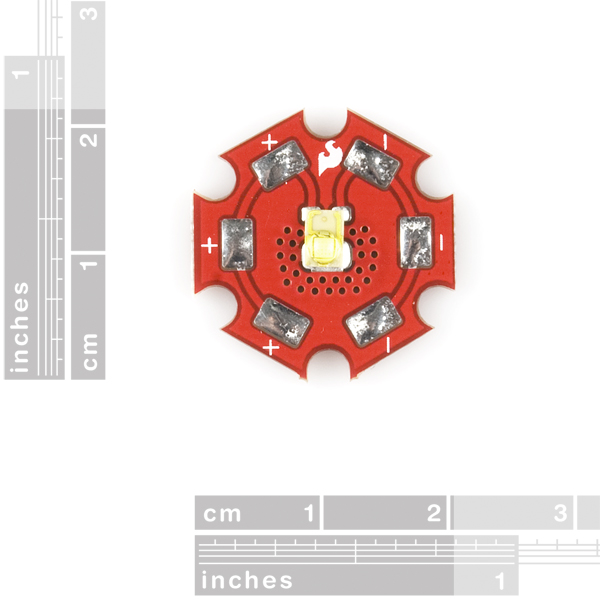
For current handling the copper can be increased to 4 oz. I got the idea for the vias from this Sparkfun PCB:
They use them to conduct heat to the back of the PCB and I see the same thing on Brushless ESC boards to increase current handling by sharing multiple traces on multi layer boards. The number could be reduced if they are larger and filled with solder.
I don't think a nylon nut would have the holding power; the threads will strip very easily and it would have to be glued down to stop it spinning in place. We could definitely use a thin jam nut to save weight though.
Wed Mar 07, 2012 1:51 pm
Valen Experienced Roboteer
Joined: 07 Jul 2004
Posts: 4436
Location: Sydney
So we made some switches with some M1.6 screws we had for another project.
6 of the bare PCB's together weighs 2 grams
6 switches with covers weighs 4 grams
our scales only measure whole grams
so roughly
switch = 0.3G
switch with polycarb cover = 0.6g
We found some stainless M1.6 screws with a socket head, they have a wider head, might give better contact and everybody prefers the allen key.
Downside is they are kinda spendy ~$1 per screw.
to clarify, you solder a wire onto the pads on either side of the bolt.
use a file or whatever to cut a channel for the wire out (because we don't know where you want the damn wires comin out)
To mount into the bot, we have a 2mm slot in the PCB and the poly, you don't need the poly, the underside of the switch is still insulated by PCB, but the poly will protect the top side and your screwdriver.
RRP is ~$5 at a guess _________________ Mechanical engineers build weapons, civil engineers build targets
You cannot post new topics in this forum You cannot reply to topics in this forum You cannot edit your posts in this forum You cannot delete your posts in this forum You cannot vote in polls in this forum

 RoboWars Australia Forum Index
-> Technical Chat
RoboWars Australia Forum Index
-> Technical Chat